Club Hits Purple Patch

The club is currently hovering around 70 members for the financial year, which is probably the largest it has ever been.  This is more than double the membership of a few years ago.

A substantial number of new members are juniors, and this bodes well for the future of the hobby.  How good is it to watch the kids enjoying this great pastime?

Much of this success can be slated home to the hard work of the committee, flying instructors, and the welcoming environment that exists at the flying field.

It’s great to see the pit area getting crowded on the weekends (if only the weather would improve…).  Those of us who sleep-in are now being banished to the sidelines.

New members are always welcome.  Come along and have a test fly on the club trainer with one of our instructors.

Building a Sports Model – Part 7

Having cleverly and irrevocably deleted many photos from the phone, some intermediate stages of the build are not recorded, which will require skipping through a large chunk of the final bit of work.

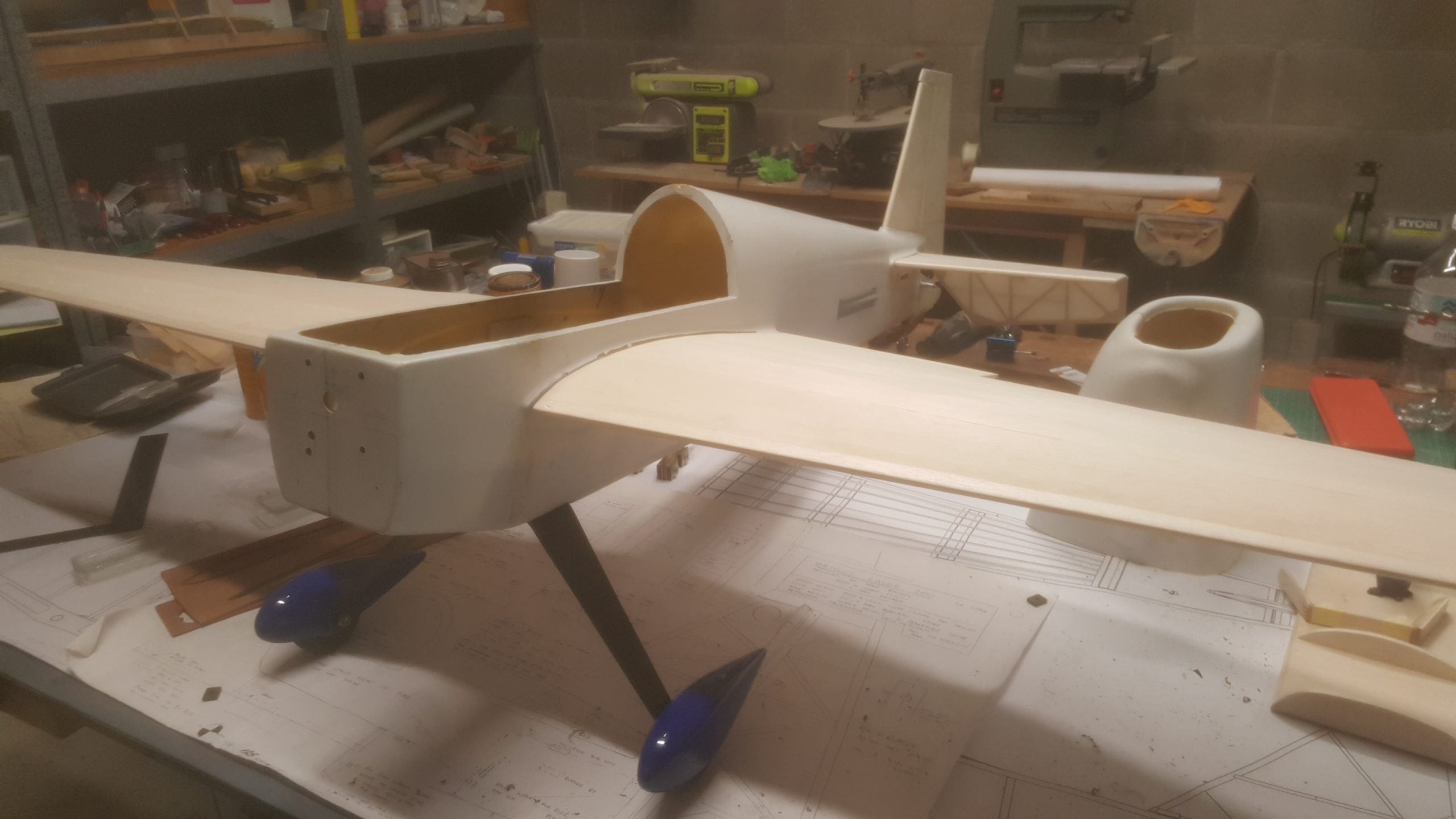
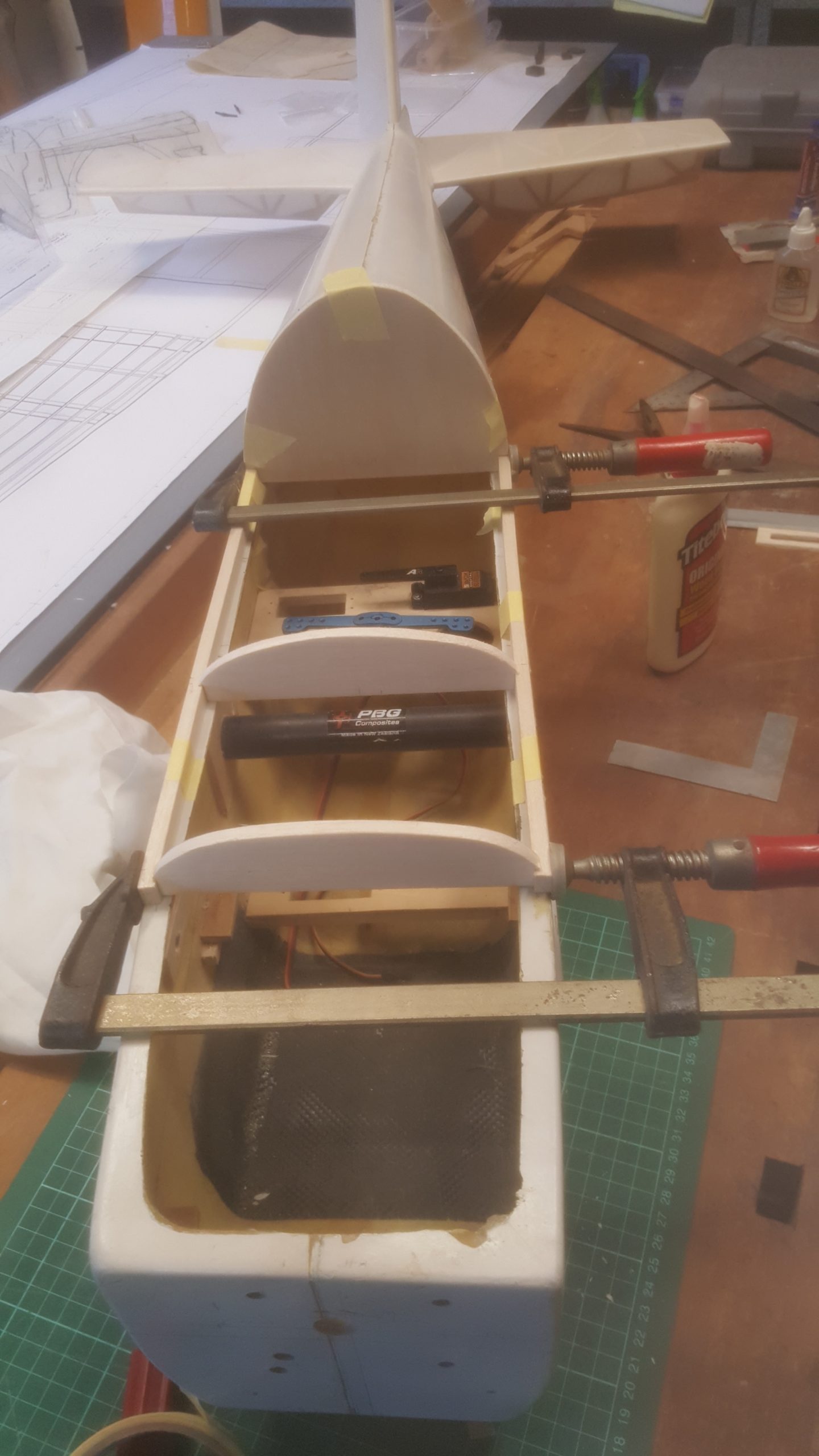
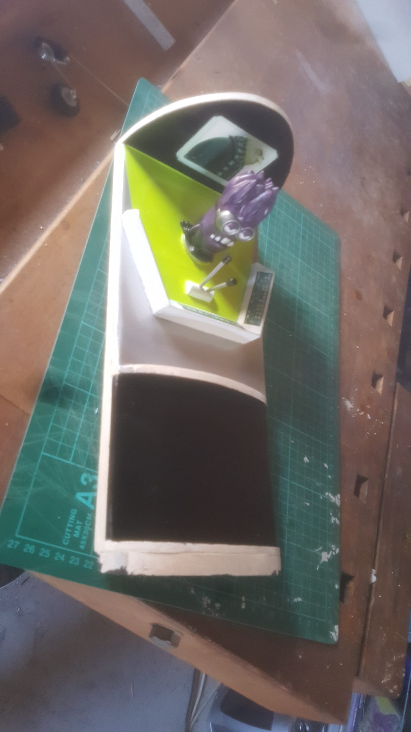
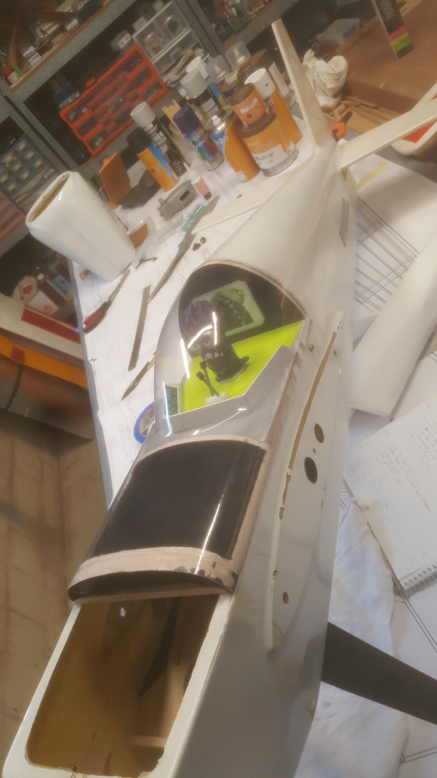
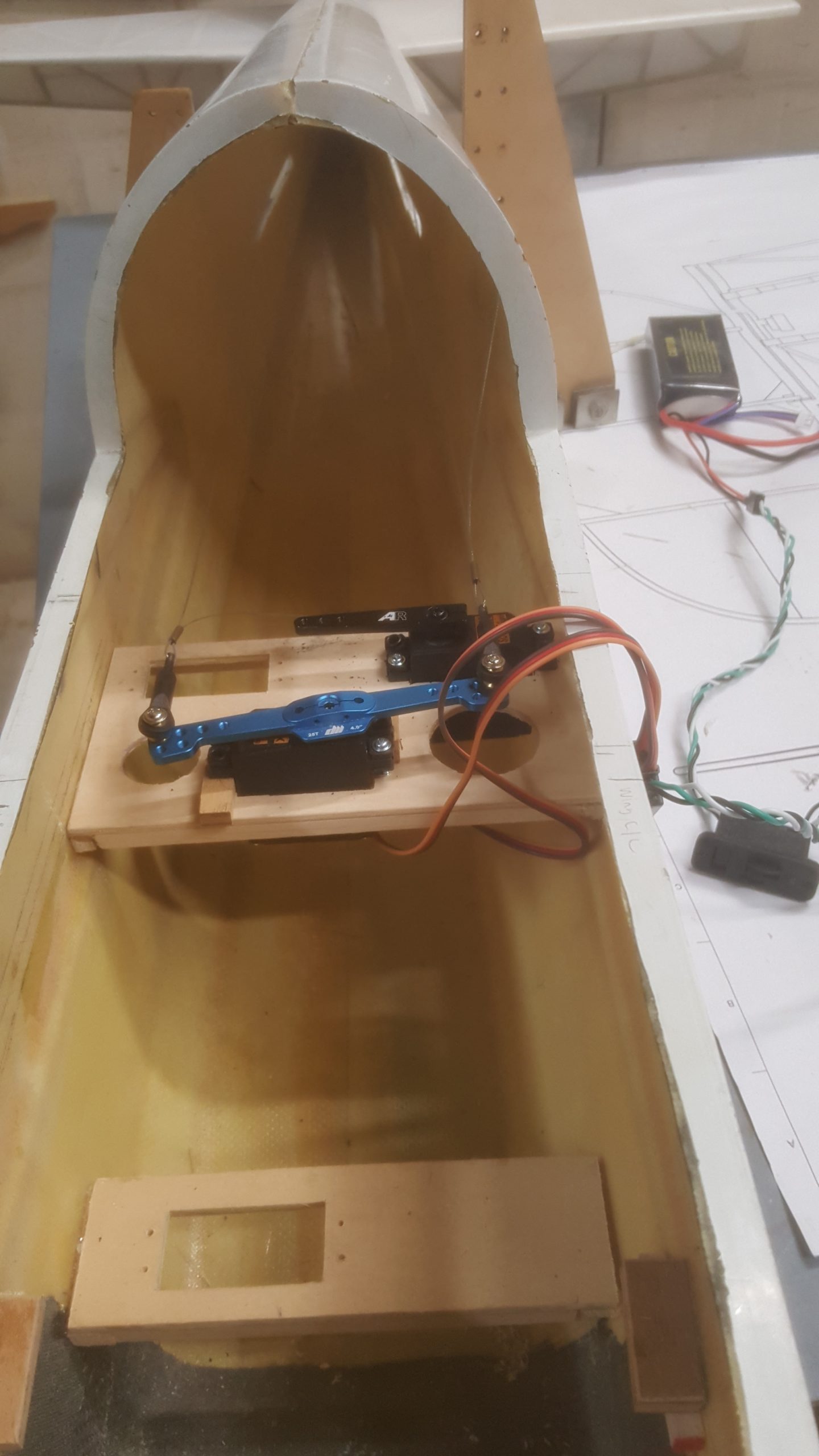
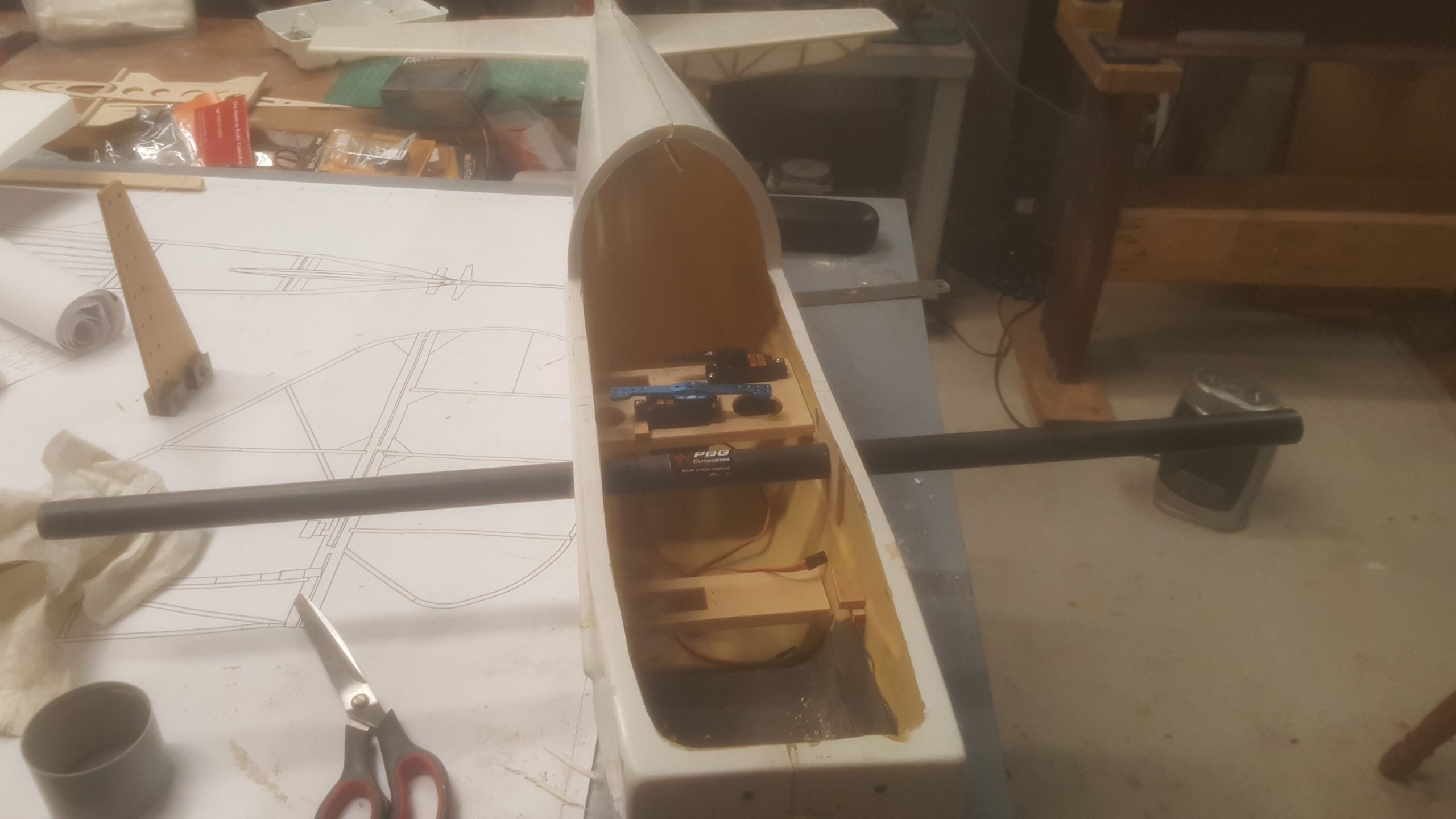
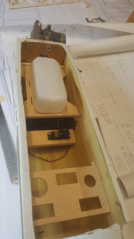
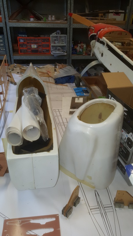
We left off with the canopy, and following that the final installations were completed for the fuel tank and radio gear, undercarriage and wheel pants.  Mounting points were fabricated for the canopy, cowling and radio switch, and cut-outs were made in the canopy for a glow stick, engine tuning and muffler clearance.  

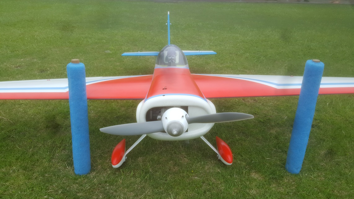
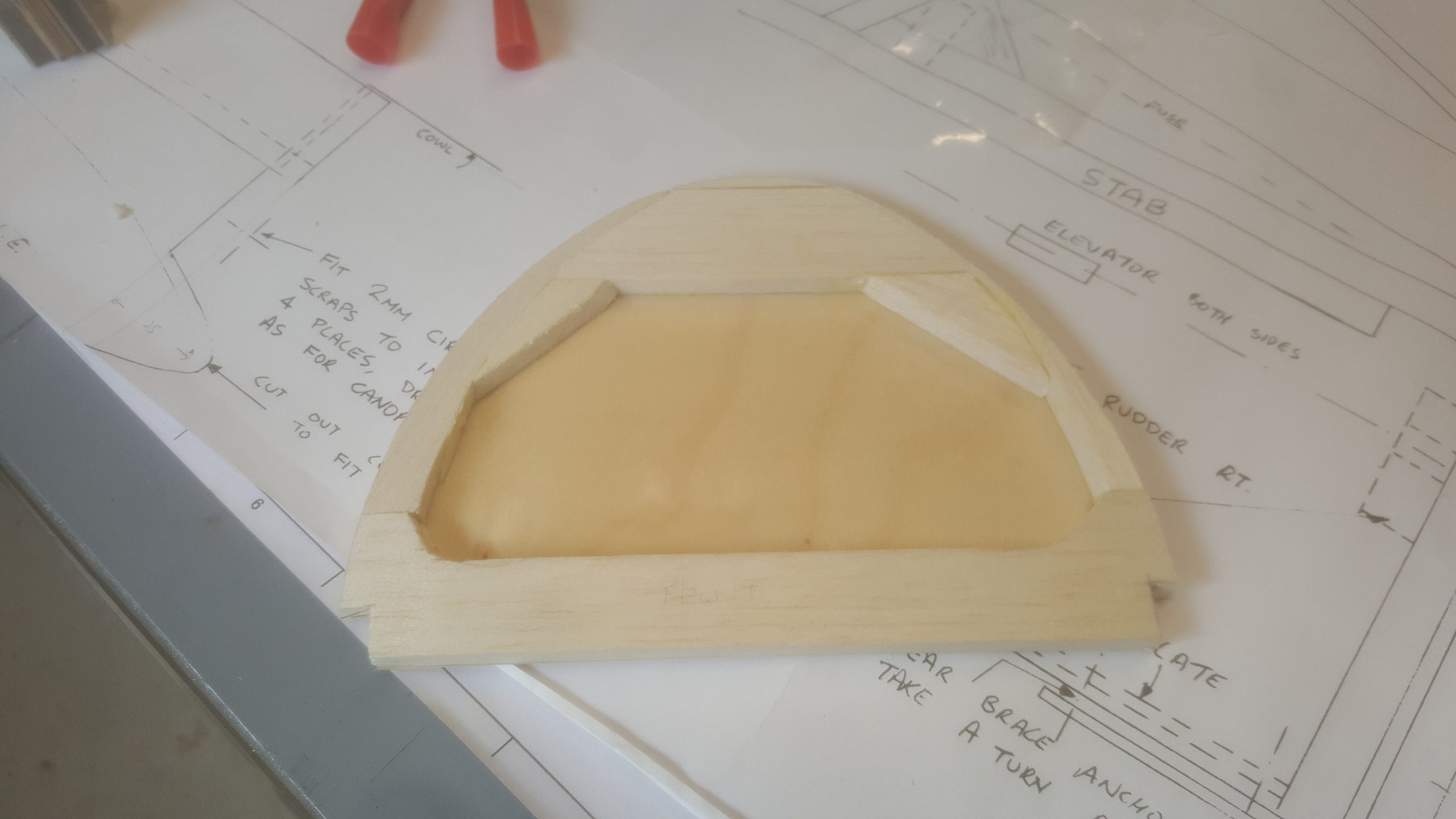
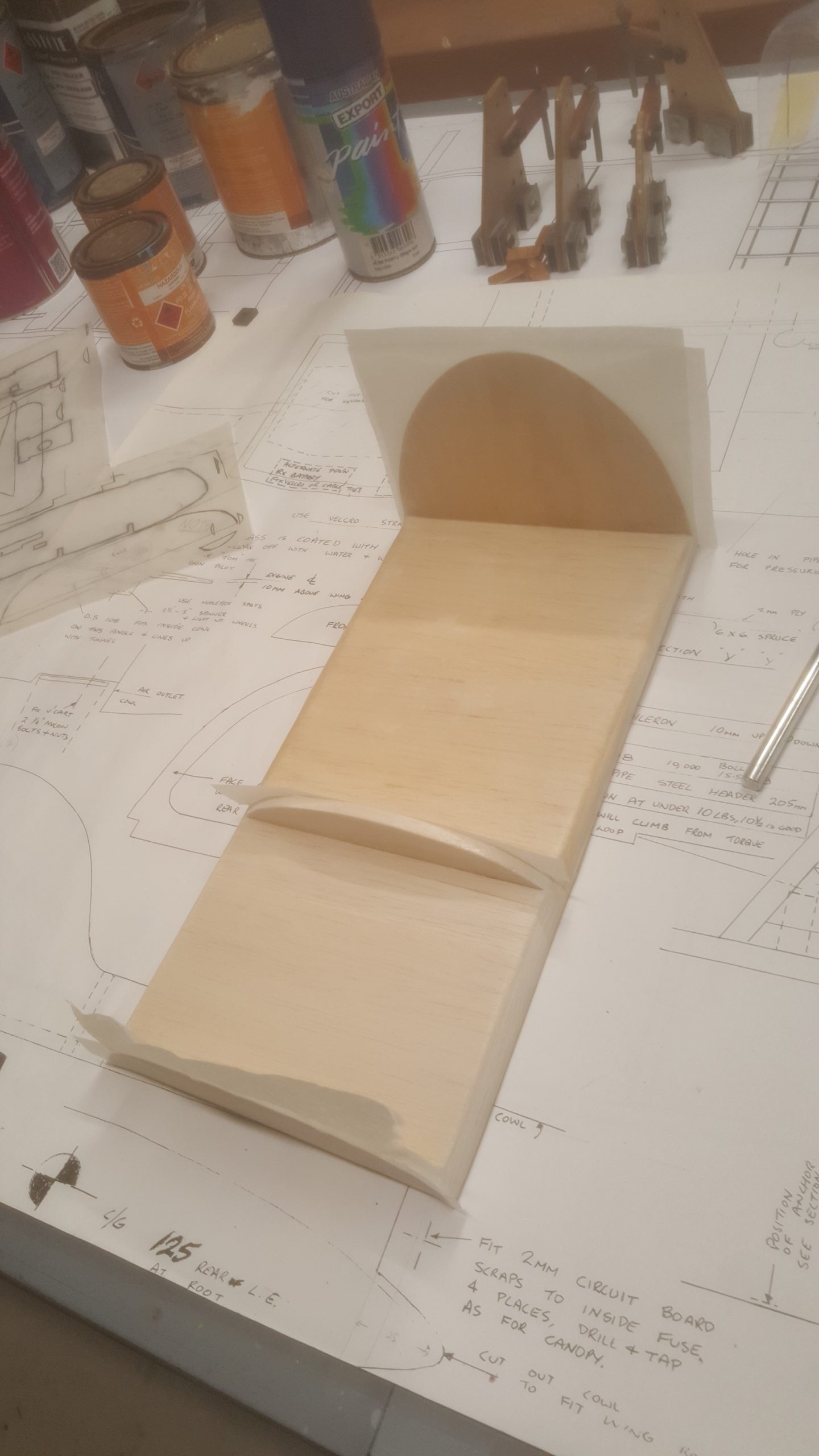
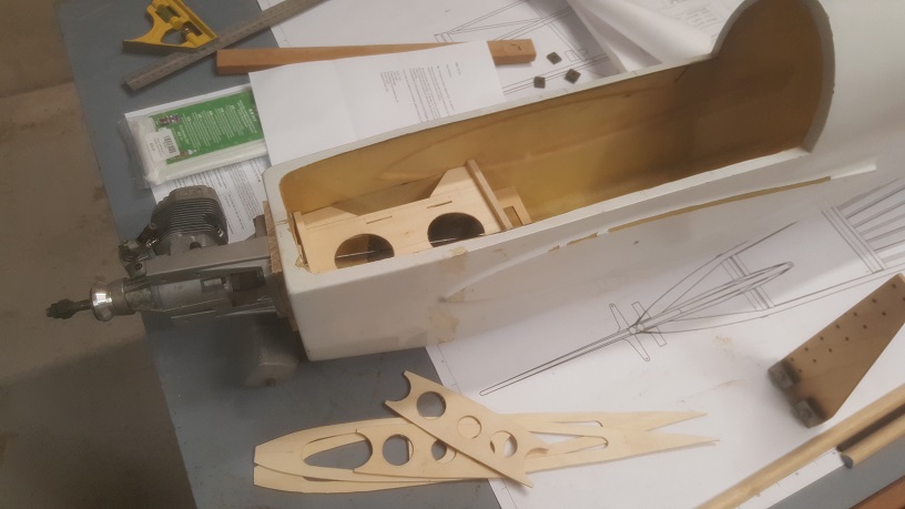
A bit of thought went in to air flow for the engine cooling, and a balsa/fibreglass baffle was glued into the front of the cowl to direct all the incoming air over the engine.  

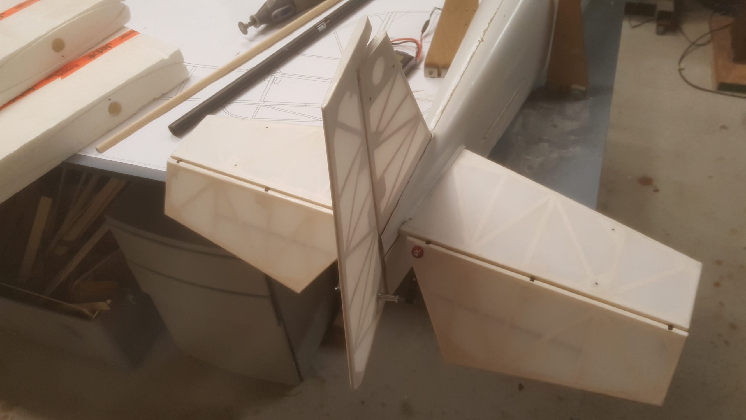
A final check was completed to make sure that everything fitted together and worked properly.  Theoretically at this point, the model was ready to fly, pending weight balancing.

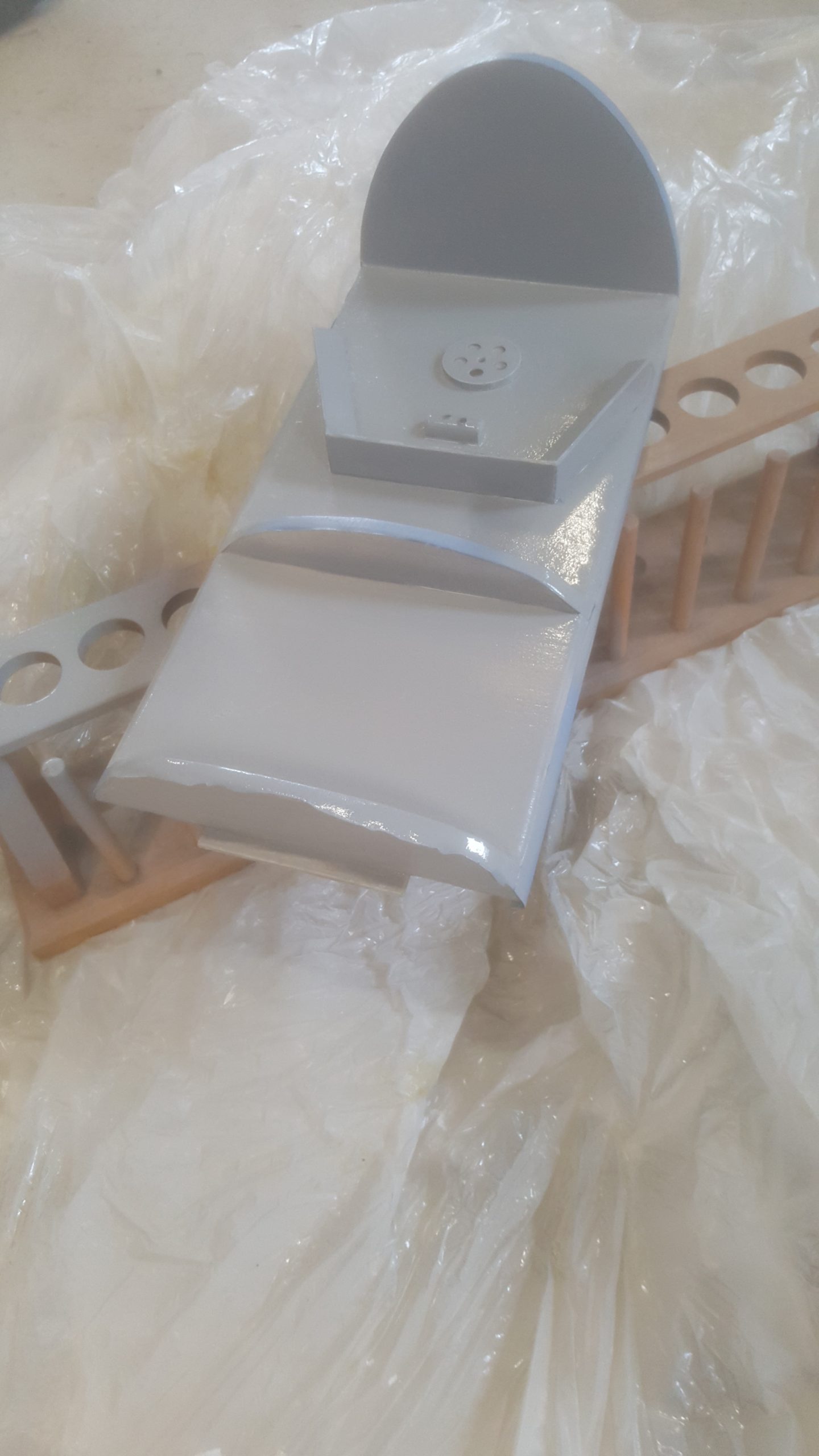
A couple of weeks were spent filling and rubbing down all the parts, especially the fuselage and cowl, fixing the dings and so forth for what was quite a weather beaten shell, thanks to its having passed through many hands over the years.  This was achieved mainly with car body filler and high lift automotive primer, and a lot of sandpaper.  Once it was ready, everything was sprayed with normal primer to provide an even base coat.

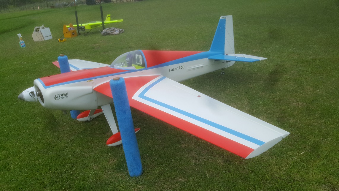
A coat of white automotive 1k acrylic paint was then sprayed on to everything.  I always use this type of paint for models as it is so easy to get a good result out of the spray gun, and the colour depth is excellent.  It’s thinners based, but I use a decent mask and gloves so that’s not a problem (yes, I actually use a mask for the purpose it was intended!).

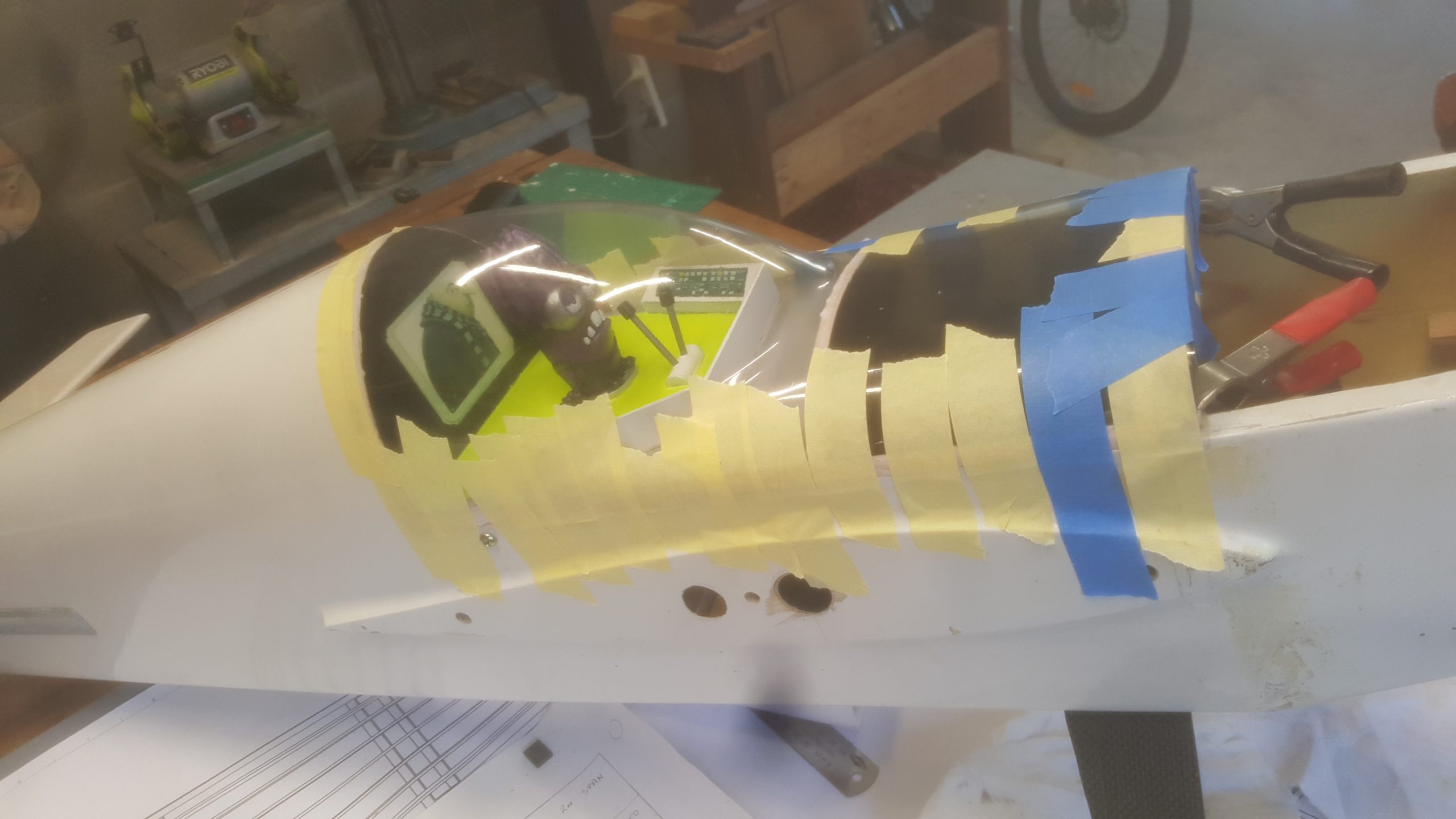
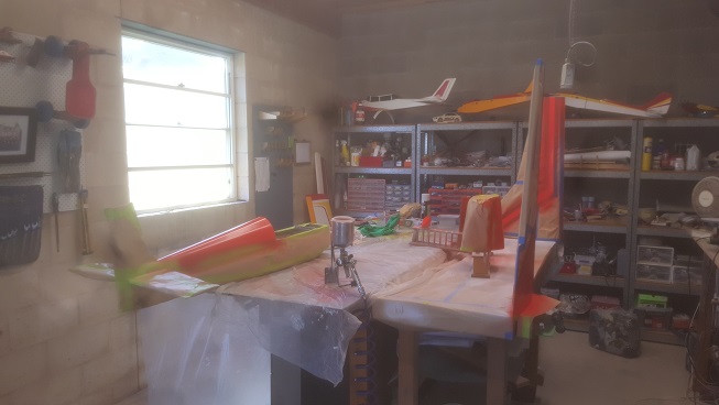
After the white came the masking and additional colour coats.  The pic below shows the model masked up and parts setup on makeshift painting mounts for the orange.  Spray painting doesn’t have to be done in a special booth, as long as you wipe everything down with a tack cloth before spraying and have a bit of ventilation.  Automotive paint flashes off very quickly, so airborne dust isn’t a problem for this standard of painting.


Finally, a 2k epoxy clear coat (basically an automotive two-pack) was sprayed over the top to provide strength and depth, and to fuel-proof the paint.

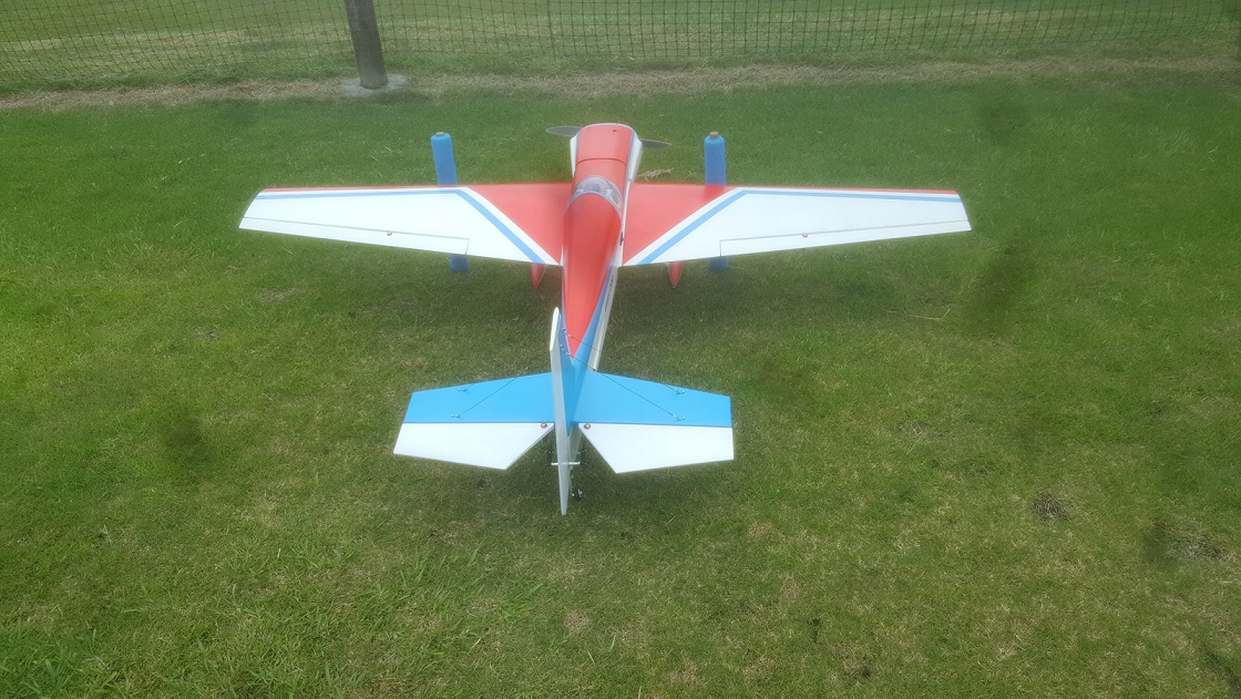
There are only three jobs left to do after that.  Reassemble the model, balance it, and test fly it!

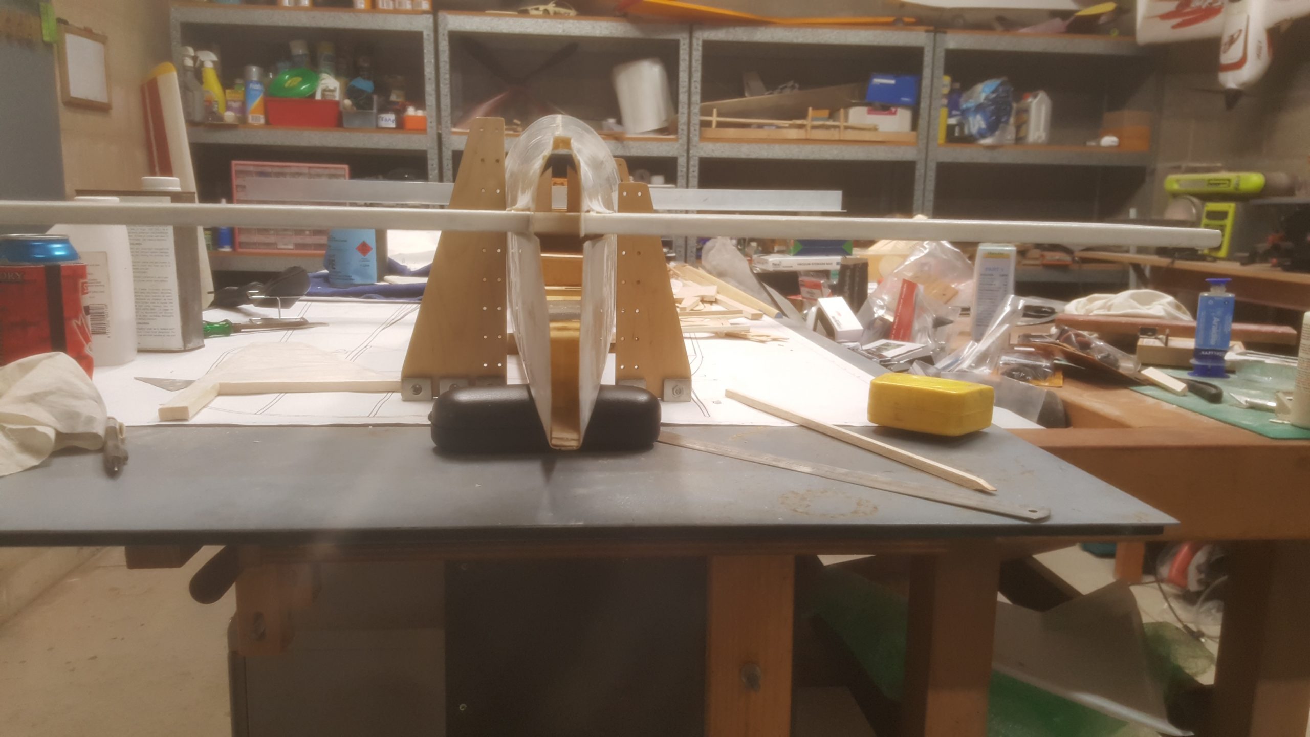
Balancing was done with a home -made Vanessa C-G Rig.  It is necessary to achieve a centre-of-gravity at between 25 – 30% of the mean wing chord for flight stability.  The pic below shows the model hanging in the Vanessa rig, which simply uses a plumb bob to determine the centre of gravity location, with the ropes adjusted so that the model is in its correct flying attitude (determined using a bubble level).  If the plumb is too far to the rear (which is usual for a new model), weight must be added to the nose.


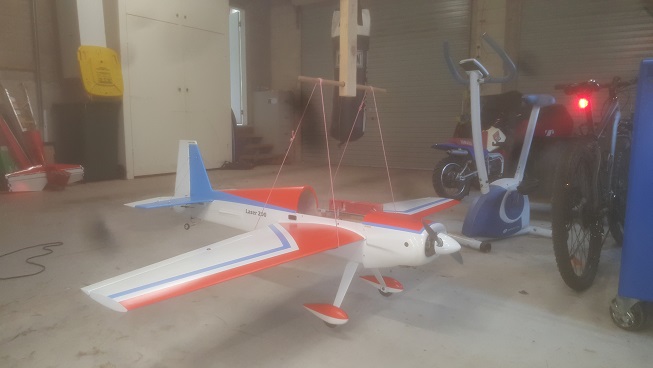
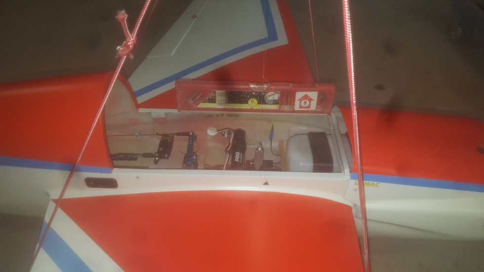
The close-up below shows the bubble level and the plumb dangling to the rear of my CoG arrow marker.  This meant adding weight to the nose, and sadly a lot more than I would have liked.  But a heavy model is preferable to an unstable one, although this is a good reminder to always build the tail light! (which I thought I had….)


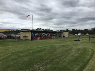
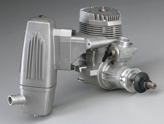
With that done, the engine was test run at the flying field.  It turned out that a new piston ring was required, but once that was fitted the OS 120AX ran nicely.


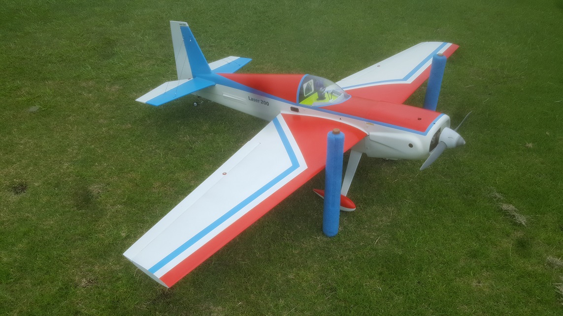
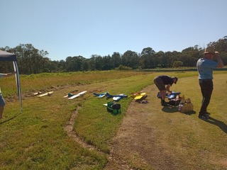
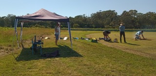
Finally the weather cleared just enough for a test flight on a much shortened, very wet runway. 


Test flights are fraught, but are the culmination of many hours of work, and are what building your own model is really all about.  To maiden an aeroplane you’ve just built is very satisfying.


Success!  The model flew nicely with minimal trim required, and was easy to land.  (We won’t talk about the incident when it disappeared momentarily behind the trees…)  Now, hopefully, I can look forward to many hours of flying fun.


2021 Christmas Party

The club Christmas Party will be held at the flying field on Saturday 11th December at 10.00am.

Members and their families are all welcome.

Bring all the planes that will fit in your car.

More Details to follow…


UPDATE

A very successful event was held with the best attendance in years.  A highlight was Grant’s slow cooked roast meat.

The weather was typically foul and windy but at least it didn’t rain, and it didn’t deter anyone.

Building a Sports Model – Part 6

The completed wings can now be test-fitted to the fuselage.  The wing tube is cut to size so that both wings can slide on fully.

With the wings now aligned, the carbon fibre undercarriage legs could be attached evenly.  They had to be cut to shape, and one side cut down, as there is a small levelling fault in the fuselage moulding at the mounting point. 

The legs were then drilled out for axles and 6mm nylon mounting bolts.  A quarter inch ply plate was glued into the fuselage to add strength to the mounting, and then there was lots of fiddling about to attached the wheels and wheel pants so that they don’t fall off mid flight. 

The tailwheel assembly was also fitted.


Next up it was time to build the canopy frame.  This consisted of three formers attached to a balsa framework.  The two front formers are balsa, and the rear is 0.5mm ply on a balsa frame.


A 1.5mm balsa base was sheeted in, the structure was sanded and then covered in tissue and dope to both seal the wood and make it look more presentable.

Some framing was added underneath to give it strength, and mounting lugs glued in place and tapped for 5mm screws.


The easy path from this point would be to give the cockpit area a quick spray with paint and move along.  But the cockpit is always the focal point of any model – good scale builders will put huge amounts of effort into their cockpits and pilot figures.

So I decided to spruce things up a bit and have a bit of fun.  A character from a kid’s movie was downloaded and 3-d printed and painted – the ‘Evil Minion’ from Despicable Me – and a very basic cockpit assembled around it.  After assembly it was painted with an undercoat, then colours, and graphics were added with decal-paper prints.


This added considerable time to the project, but it will result in a much more aesthetic product.

With that done the canopy was glued in place and cut to size, very kindly sent to me by the manufacturers of these kits in New Zealand.


Building a Sports Model – Part 5

The root  ribs are cut from 1.5mm ply and glued to the foam wing cores.  Also included are a 5mm bolt for mounting to the fuselage and two locator lugs made from leftover carbon-fibre rods.

The wings are now ready for sheeting with 1.5mm balsa.  First the sheets need to be glued together along their edges.  They are taped together, flipped over and yellow glue applied along the joins, then weighted down while they dry.

Gluing the sheets to the foam wings can be tricky, as it’s very important to get a consistent bond.  But with the right tools it’s actually very easy.  

Yellow glue is spread with scrap balsa like butter to cover every bit of foam.  The balsa is laid in place hard up against the leading edge, and now for the tricky part.  The wing is inserted into a giant vacuum bag from Bunnings, and the air sucked out and left to dry overnight.  Clever eh?  Perfect results every time.

Do that with the other three sides, trim the edges, and the wings are now super strong and light.


That was the easy part.  Now the aileron servo cutouts have to be made, lined with balsa, and the servos mounted on hardwood blocks. 

Then the ailerons need to be carefully measured and cut out.  12mm balsa spars are added to the trailing edge cutout and the aileron leading edge, then sanded to shape.  Hinges are installed and balsa blocks glued in for the aileron horns, which are then fitted.  A quick check with the receiver connected to make sure everything works, then pull it apart again.

The blurred photo below shows the end ribs being glued on.  Note the small cross on the wing for the servo cutout.  The ailerons process was so involved that I forgot to take photos.  

Building a Sports Model – Part 4

The servo rack was installed into the fuselage with a couple of Savox servos.  The rudder wires can be seen attached for initial fit testing.


Below, the wing tube and other holes were drilled and the wing spar tube aligned and glued in place


Less than three months after replacing my phone camera lens I’ve broken it again, so all the photos are going to be a little hazy.

While waiting on the canopy to arrive, it was time to get the wings sorted out.

The foam cores needed a strip of fibreglass glued to the top and bottom trailing edges to give them strength, and balsa leading edges were glued on.

A hole had to be measured and cut under the wings for the aileron servos, as well as for the centre plywood rib which was glued in.


Now a rather tricky hole had to be made through the wing to the servo cutout for the servo cable to access the receiver in the fuselage.

For these the tip of a 12mm steel rod was heated with a blowtorch, placed into a rough jig and rammed through the wing, melting the foam as it went.  

It’s a lot easier than it sounds really.

Building a Sports Model – Part 3

I know how excited everybody is for the next instalment, but I must insist on patience as these things take time.  What with all the fan mail I receive from on-line casino owners and Russian women making marriage proposals – sorry but there’s only so much of me to go around.

The tail feathers were the next step, and they were a lot of work.  First they were framed up from 10mm balsa, then hinges and control horns set up, and mounting points for bracing wire added.  The wood was filled and sanded to shape.


The framework was covered with an acetate lining material called Bemsilk, glued and sealed with aircraft dope.  Very cheap and effective.

After adding a balsa mounting block to the fuselage, the horizontal stabiliser was carefully glued in place, making sure it is aligned in all 3 dimensions, and especially parallel with the wings.  The aluminium bar represents the sit of the wing.  


It might look off-balance in the pic, but it’s just a dodgy photo.

The vertical fin is then glued in place square with the horizontal stabiliser and in line with the fuselage centre-line.


That’s another major job completed.

Next was to install the control systems and servo rack for the tail.  The rudder will use a pull-pull system, and for the elevators I made up a double-pronged carbon-fibre pushrod.

To be continued…

Building a Sports Model – Part 2

Before a model starts to look pretty, a lot of work has to go into installations.

First to the business end of the model, and mounting the engine.  The plans call for an offset engine mount, about 2.5 degrees to the right, which helps to deal with engine torque that tends to roll the aircraft to the left and can cause catastrophic tip stalling on take-off.  A shim was made from hardwood to sit behind the engine mount, and the engine mount centreline is shifted 7mm to the left so that the prop hub remains in line with the centre of the fuselage.

From the picture you might be able to see how neatly the muffler tucks underneath the side-mounted motor – a  perfect arrangement.  The whole lot is hidden inside the cowl. This might seem trivial but experienced builders will know why it’s exciting.

A 6mm ply firewall was also glued inside the model as the one built into the fibreglass is way too thin.  The engine mount is held in place with 5mm screws that go into blind nuts epoxied into the firewall.    That’s probably the trickiest part of the build completed.

Behind the firewall you can see a 1.5mm ply tank mount that will be screwed onto ply brackets, which are epoxied to the fuselage.  The 20oz tank will be held down with two velcro strips (you can see the velcro slots).

(The ribs in front were cut from 1.5mm ply in preparation for the wing construction while waiting for glue to dry).

Above is a view from inside showing the tank placement and throttle servo.  Behind that is the servo tray installed for the rudder and elevators from 3mm ply.

The throttle servo is connected to the carburettor with 4-40 threaded rod, which is joined to a 6mm spruce rod for stiffness.

I immediately adjusted the servo throws to prevent any future damage.  The servo end points were initially set to 50% each way, then graduated up from there to achieve a fully open and fully closed throttle.  This is all very easy with modern computerised radio transmitters.

Building a Sports Model – Part 1

With our myriad fans clamouring for more website posts, it’s time to show the masses what goes into building a flying model aircraft.

After asking around the club for a ready-to-fly, easy-going, 60 size sports model, I was handed the exact opposite: a fibreglass short kit for a 30cc IMAC stunt model. (IMAC is a competition class for more-or-less, mostly less, scale aerobatic aircraft).

But to be honest I wasn’t sorry – things like this don’t come your way every day, and a kit like this is pretty rare.

The model is a Laser 200 with a 2 metre wing span, and it comes from PBG Composites in New Zealand.  It must have been stuck in a time capsule because they seem to have stopped making them at least 10 years ago.

Above – the real thing


Below – short kit  – fibreglass fuselage and engine cowl, plans, undercarriage, neat carbon fibre wing joiner


Below – foam wing cores

The first question to ask of a nascent model is what sort of power plant it desires.  These days electric motors are popular but not with me.  A 30cc petrol motor would be the usual choice here, but a glow-plug motor is much lighter, smaller and simpler, so I picked up a second hand OS 1.20 to run a 16 x 8 prop.

And I’m glad I did because these are fantastically well sorted motors – amazingly compact with a power muffler that has a very neat attachment for changing its position.

Then there is all the other hardware and materials to purchase.  A dozen sheets of balsa for wing skins, a sheet of 1.5mm ply, 10mm balsa, fibreglass cloth, engine mount…

Below – the stuff required: fuel tank, servo arms, servos, wheels, tail-wheel, control horns, spinner, propellers, wing leading edges, control hinges, battery, s-bus terminal, receiver…

…and now we’re ready to build.